7.1 KiB
path_extrude
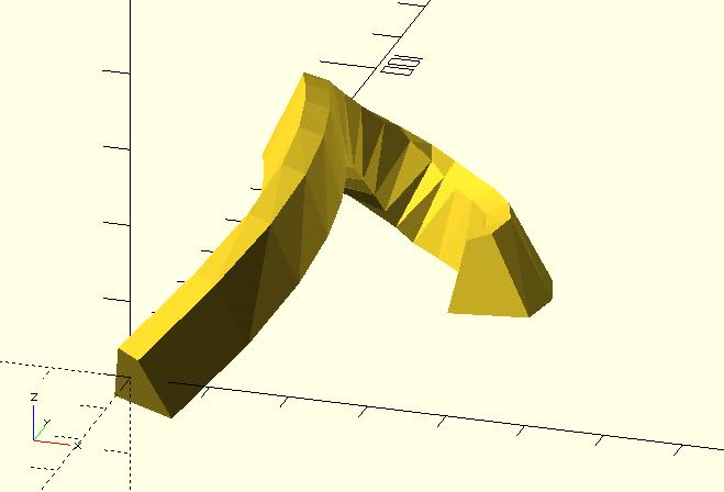
It extrudes a 2D shape along a path. This module is suitable for a path created by a continuous function.
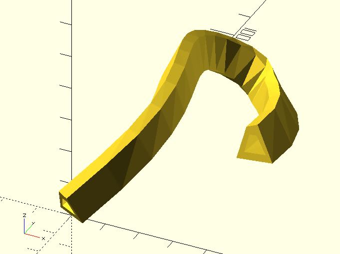
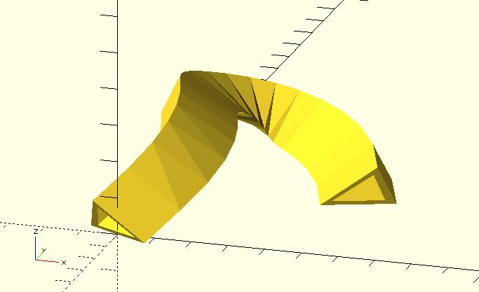
When using this module, you should use points to represent the 2D shape. If your 2D shape is not solid, indexes of triangles are required. See sweep for details.
Parameters
shape_pts: A list of points represent a shape. See the example below.path_pts: A list of points represent the path.triangles:"SOLID"(default),"HOLLOW"or user-defined indexes. See example below.twist: The number of degrees of through which the shape is extruded.scale: Scales the 2D shape by this value over the length of the extrusion. Scale can be a scalar or a vector.closed: If the first point and the last point ofpath_ptshas the same coordinate, settingclosedtotruewill connect them automatically.method: Which method doespath_extrudetake to guess how to generate sections? It accepts two value,"AXIS_ANGLE"(default) and"EULER_ANGLE". Since: 1.3.
Examples
use <path_extrude.scad>;
use <bezier_curve.scad>;

t_step = 0.05;
width = 2;

p0 = [0, 0, 0];
p1 = [40, 60, 35];
p2 = [-50, 70, 0];
p3 = [20, 150, -35];
p4 = [30, 50, -3];

shape_pts = [
	[5, -5],
	[3, 4],
	[0, 5],
	[-5, -5]
];

path_pts = bezier_curve(t_step,
	[p0, p1, p2, p3, p4]
);

path_extrude(shape_pts, path_pts);
use <path_extrude.scad>;
use <bezier_curve.scad>;

t_step = 0.05;

p0 = [0, 0, 0];
p1 = [40, 60, 35];
p2 = [-50, 70, 0];
p3 = [20, 150, -35];
p4 = [30, 50, -3];

shape_pts = [
	// outer
	[5, 0],
	[3, 9],
	[0, 10],
	[-5, 0],
	// inner
	[3, 2],
	[2, 7],
	[0, 7],
	[-3, 2]
];

path_pts = bezier_curve(t_step,
	[p0, p1, p2, p3, p4]
);

path_extrude(shape_pts, path_pts, triangles = "HOLLOW");
use <path_extrude.scad>;
use <bezier_curve.scad>;

t_step = 0.05;

p0 = [0, 0, 0];
p1 = [40, 60, 35];
p2 = [-50, 70, 0];
p3 = [20, 150, -5];
p4 = [50, 50, -3];

shape_pts = [
    // outer
    [10, 0],
    [-5, 10],
    [-10, 0],
    // inner
    [7, 1],
    [-4, 8],
    [-7, 1]
];

path_pts = bezier_curve(t_step,
    [p0, p1, p2, p3, p4]
);

path_extrude(
    shape_pts,
    path_pts,
    triangles = [
        [0, 4, 3],
        [0, 1, 4],
        [1, 5, 4],
        [1, 2, 5],
        [2, 3, 5],
        [2, 0, 3]
    ]
);
About path_extrude (Important!!)
path_extrude is actually a workaround when you have/provide only path points.
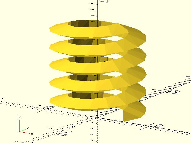
If you want to extrude a shape along a path precisely, providing enough information about how to rotate sections is necessary. If you want to extrude a shape along a helix, helix_extrude is more suitable because it knows how to dig out necessary data for rotating sections precisely.
use <helix_extrude.scad>;

shape_pts = [
	[0,0],
	[3, 1],
	[0, 2]
];

helix_extrude(shape_pts,
	radius = 5,
	levels = 5,
	level_dist = 3,
	vt_dir = "SPI_UP"
);
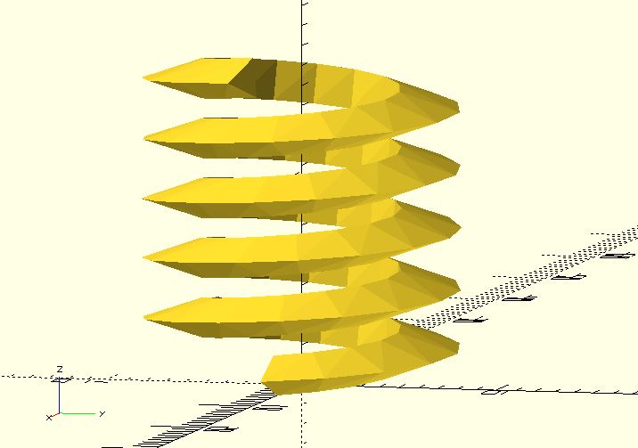
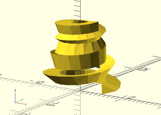
If you have only points, what path_extrude can do is to guess data about rotations. The different algorithm will dig out different data. For example:
use <helix.scad>;
use <path_extrude.scad>;

shape_pts = [
	[0,0],
	[3, 1],
	[0, 2]
];

points = helix(
	radius = 5,
	levels = 5,
	level_dist = 3,
	vt_dir = "SPI_UP"
);

path_extrude(shape_pts, points);
You might think this is wrong. Actually, it's not. It's the correct/default behavior of path_extrude. Because you don't provide other information, what path_extrude can do is to guess how to generate sections from points. You think it's a bug in path_extrude because your brain has information that path points do not provide.
The method parameter is default to "AXIS_ANGLE", a way to guess information from points. It accepts "EULER_ANGLE", too.
use <helix.scad>;
use <path_extrude.scad>;

shape_pts = [
	[0,0],
	[3, 1],
	[0, 2]
];

points = helix(
	radius = 5,
	levels = 5,
	level_dist = 3,
	vt_dir = "SPI_UP"
);

path_extrude(shape_pts, points, method = "EULER_ANGLE");
"EULER_ANGLE" generates the same section at the same point. You might think the model is correct. But, that's because what it guesses from points just match your expectation.
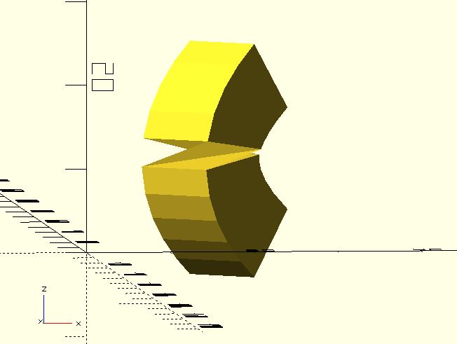
"EULER_ANGLE" will generate an abrupt when the path is exactly vertical. The problem happened in (older) Blender, too.
use <path_extrude.scad>;

shape_pts = [[5, -5], [5, 5], [-5, 5], [-5, -5]];

path_pts = [
	[20, 20, 0],
	[18.2, 18.2, 2],
	[16.8, 16.8, 4],
	[15.8, 15.8, 6],
	[15.2, 15.2, 8],
	[15, 15, 10],
	[15.2, 15.2, 12],
	[15.8, 15.8, 14],
	[16.8, 16.8, 16],
	[18.2, 18.2, 18],
	[20, 20, 20]
];

path_extrude(shape_pts, path_pts, method = "EULER_ANGLE");
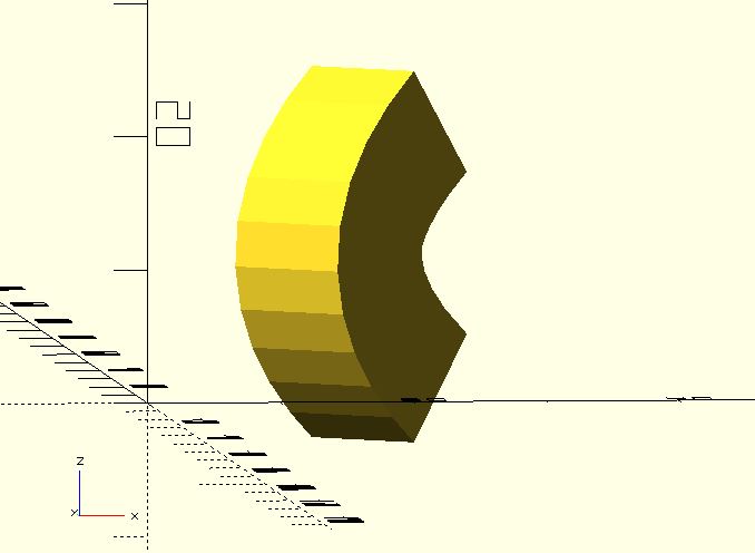
The problem doesn't happen when method is "AXIS_ANGLE".
use <path_extrude.scad>;

shape_pts = [[5, -5], [5, 5], [-5, 5], [-5, -5]];

path_pts = [
	[20, 20, 0],
	[18.2, 18.2, 2],
	[16.8, 16.8, 4],
	[15.8, 15.8, 6],
	[15.2, 15.2, 8],
	[15, 15, 10],
	[15.2, 15.2, 12],
	[15.8, 15.8, 14],
	[16.8, 16.8, 16],
	[18.2, 18.2, 18],
	[20, 20, 20]
];

path_extrude(shape_pts, path_pts, method = "AXIS_ANGLE");
So, which is the correct method? Both methods are correct when you provide only points. method is just a way you tell path_extrude how to guess more information when extruding.
"EULER_ANGLE" will generate an abrupt when the path is exactly vertical. Some users might think it's a bug so "AXIS_ANGLE" is the default value.
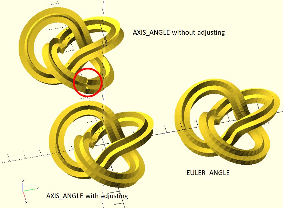
"EULER_ANGLE", however, generates the same section at the same point. This means that you don't have to adjust sections if you want to extrude along a closed path. It's an advantage when extruding. For example:
use <shape_pentagram.scad>;
use <path_extrude.scad>;
use <torus_knot.scad>;

p = 2;
q = 3;
phi_step = 0.05;
star_radius = 0.5;

pts = torus_knot(p, q, phi_step);

shape_pentagram_pts = shape_pentagram(star_radius);

// not closed perfectly
translate([-8, 0, 0]) path_extrude(
	shape_pentagram_pts,
	concat(pts, [pts[0]]),
	closed = true,
	method = "AXIS_ANGLE"
);

// adjust it
path_extrude(
	shape_pentagram_pts,
	concat(pts, [pts[0]]),
	closed = true,
	twist = 188,
	method = "AXIS_ANGLE"
);

// "EULER_ANGLE" is easy in this situation
translate([0, 8, 0]) path_extrude(
	shape_pentagram_pts,
	concat(pts, [pts[0]]),
	closed = true,
	method = "EULER_ANGLE"
);
Both methods are useful. If "AXIS_ANGLE" doesn't guess out what you want, choose "EULER_ANGLE", and vice versa.
